MIL-DTL-9415B
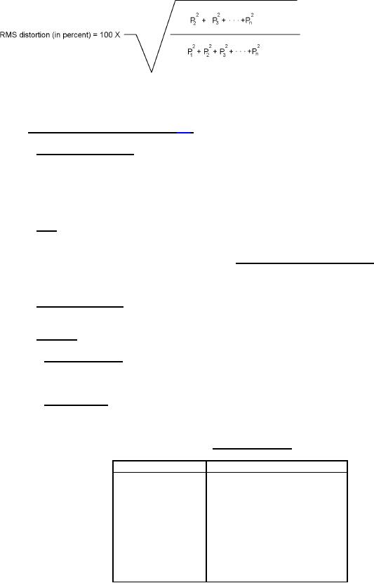
4.5.2.1.9 Distortion-frequency characteristic. The harmonic distortion in the acoustic output of the loudspeaker at
a certain frequency of the fundamental shall be determined by the following formula:
Where P1 is the pressure amplitude of the fundamental, and P2, P3, P4, et cetera are the pressure amplitudes of
the harmonic components in the output, or by using a total distortion analyzer (see 3.4.2.3.7).
4.5.2.2 AF amplifier AM-492B/AIC-10 (see 3.5).
4.5.2.2.1 General test conditions. Test circuit connections shall be specified on figure 6. Unless otherwise
specified, a 150-ohm resistor shall be connected across the input terminals of the amplifier, and an 8-ohm resistor
shall be connected across the output terminals of the amplifier. In making performance measurements with terminals
of the amplifier in the normal condition, the ON-OFF switch of the LS-184A/AIC-10 shall be in the ON position, and
Switch S-3201 of the test circuit shall be open. In making performance measurements in the call condition, the ON-
OFF switch of the LS-184A/AIC-10 shall be in the OFF position, and Switch S-3201 of the test circuit shall be closed.
4.5.2.2.2 Gain. Bridging gain shall be determined by the following relationship (see 3.5.2.1).
Power delivered by amplifier
Gain = 10 log10
X
_____to 8-ohm load resistor
Power input to 150-ohm resistor
across amplifier input terminals
4.5.2.2.3 Frequency response. Measurements shall be made with a constant signal input of 2 volts. In individual
4.5.2.2.4 Distortion.
4.5.2.2.4.1 Distortion (normal). Measurements shall be made under the conditions indicated herein. In individual
tests, distortion shall be checked at an output voltage of 2.5 volts. (This may be done by viewing an oscilloscope,
resorting to the use of a distortion analyzer only in questionable cases) (see 3.5.1.3).
4.5.2.2.4.2 Distortion (call). Measurements shall be made under the conditions indicated herein. In individual
tests, distortion shall be checked at an output voltage of 2.5 volts. (This may be done by viewing an oscilloscope,
resorting to the use of a distortion analyzer only in questionable cases) (see 3.5.2.3).
TABLE X. Signal input-output.
Signal input in volts
Output in dB relative to 1.0 volt
2.0
-1.0 to +2.0
2.5
1.0 to 4.0
3.0
2.8 to 5.8
4.0
5.0 to 8.0
4.5
6.0 to 9.0
5.0
6.6 to 9.6
6.0
7.4 to 10.2
7.0
8.2 to 11.0
8.0
9.5 to 12.5
12.0
12.5 to 15.0
20
For Parts Inquires call Parts Hangar, Inc (727) 493-0744
© Copyright 2015 Integrated Publishing, Inc.
A Service Disabled Veteran Owned Small Business