MIL-PRF-26542/10C
NOTES:
1. Dimensions are in inches. Tolerances are ± .015 inches, ± 2 degrees of angle, unless otherwise
specified.
2. Quantity and configuration of sound apertures is optional.
3. Location of marking on surface shown is optional.
4. Set-screws shall hold the microphone securely to the cable assembly, be of slotted or Allen type,
and recessed.
5. Metric equivalents are given for general information only and are based upon 1 inch = 25.4 mm.
FIGURE 1. Microphone assembly - Continued.
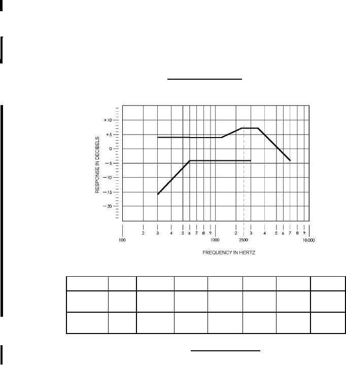
Frequency
points (Hz)
300
600
1,400
2,300
3,000
3,500
7,000
Upper
Limits
+4.0
+4.0
+4.0
+7.0
+7.0
+7.0
+1.0
(dB)
Lower
Limits
-16.0
-4.0
-4.0
-4.0
-4.0
------------
-------------
(dB)
FIGURE 2. Frequency response.
REQUIREMENTS:
Component parts:
Microphone element: Shall be in accordance with figure 1.
2
For Parts Inquires call Parts Hangar, Inc (727) 493-0744
© Copyright 2015 Integrated Publishing, Inc.
A Service Disabled Veteran Owned Small Business