MIL-DTL-12606E
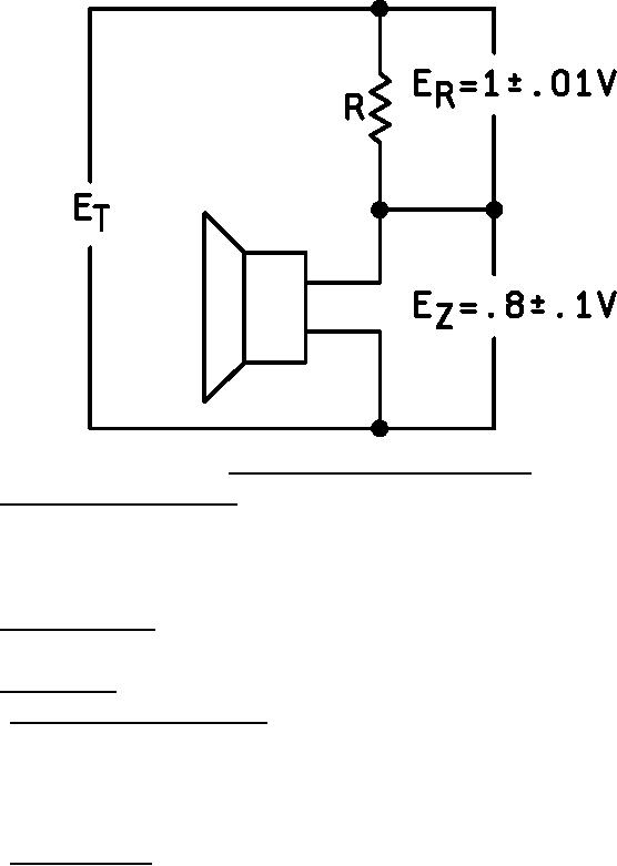
FIGURE 6. Measurement of impedance by direct reading method.
4.7.4 Dielectric withstanding voltage (see 3.4.3). The loudspeaker shall be tested in accordance with method 301 of
MIL-STD-202. The following details shall apply:
a. Test voltage 400 volts.
b. Nature of potential 60 Hz, AC.
c. Points of application The test voltage shall be applied between one of the voice coil terminals and the loudspeaker frame;
simultaneously, the voice coil shall be excited with a minimum of 2.85 volts root mean square (rms) at 300 Hz.
4.7.5 Acoustic quality (see 3.4.4). A constant voltage having a rms value of 4.00 ± .1 volts shall be applied to the voice coil terminals
and the frequency varied continuously from 300 to 7,000 Hz and back to 300 Hz. For M12606-01, the frequency shall be varied
continuously from 400 to 6,000 Hz and back to 400 Hz.
4.7.6 Frequency response.
4.7.6.1 Type LS-445/U and M12606-02 (see 3.4.5.1). The loudspeaker shall be mounted in a test cabinet (see figure 7) and placed 3
feet from a calibrated Western Electric Type 640AA (or equal) condenser microphone and amplifier. The microphone shall be placed on
the axis of the loudspeaker. A constant voltage having a rms value of 4.00 ± .1 volts shall be applied to the voice coil terminals and the
frequency varied continuously from 300 to 7,000 Hz. The acoustic output shall be recorded on a direct-writing strip graph chart using an
automatic plotter or curve tracer, with a minimum writing speed of 10 inches per second and a maximum chart speed of 30 inches per
minute. Or, at the option of the manufacturer, point-to-point measurements may be made, every 50 Hz from 300 to 600; every 100 Hz
from 600 to 1,500 Hz; every 250 Hz from 1,500 to 2,000 Hz; every 100 Hz from 2,000 Hz to 2,500 Hz; every 250 Hz from 2,500 to 3,000
Hz; every 500 Hz from 3,000 to 7,000 Hz, with the data record and a graph drawn (see figure 4).
4.7.6.2 M12606-01 (see 3.4.5.2). The loudspeaker shall be mounted in a closed 5 x 5 x 3 inch test cabinet with suitable 2-3/4 inch
diameter loudspeaker opening and placed 3 feet from a calibrated Western Electric Type 640AA (or equal) condenser microphone and
amplifier. The microphone shall be placed on the axis of the loudspeaker. A constant voltage having a rms value of 4.00 ± .1 volts shall
be applied to the voice coil terminals and the frequency varied continuously from 400 to 6,000 Hz. The acoustic output shall be recorded
on a direct-writing strip graph chart using an automatic plotter or curve tracer with, a minimum writing speed of 10 inches per second and
a maximum chart speed on 30 inches per minute. Or, at the option of the manufacturer, point-to-point measurements may be made every
50 Hz from 400 to 600 Hz; every 100 Hz from 600 to 1,500 Hz; every 250 Hz from 1,500 to 2,000 Hz; every 100 Hz from 2,000 to 2,500
Hz; every 250 Hz from 2,500 to 3,000 Hz; and every 500 Hz from 3,000 to 6,000 Hz, with the data recorded and a graph drawn (see
figure 5).
15
For Parts Inquires call Parts Hangar, Inc (727) 493-0744
© Copyright 2015 Integrated Publishing, Inc.
A Service Disabled Veteran Owned Small Business