MIL-DTL-9415B
4.4.2.2 Sampling plan. Accept on zero, for general inspection as specified in table VIII.
TABLE VIII. Sampling plan.
Lot size
Sample size
2
to
8
1/
13 1/
9
to
15
16
to
25
13
13
26
to
50
51
to
90
13
91
to
150
13
151
to
280
20
281
to
500
29
501
to 1,200
34
1,201
to 3,200
42
1/ Indicates entire lot must be inspected or sample size not to exceed lot size.
4.5 Test procedures
4.5.1 Mechanical inspection. Dynamic Loudspeaker LS-184A/AIC-10 and its component parts shall be thoroughly
inspected and their dimensions measured to determine conformance to the requirements of this specification with
respect to materials, workmanship, mechanical detail, and finishes prior to and during assembly. Particular attention
shall be paid to the width and concentricity of air gap, cleanliness of air gap, clearance and concentricity of voice coil
in the air gap, terminal and tubing of loudspeaker lead wire, polarity marking of connector terminals and terminal
board, freedom from loose particles, voice coil lead dress, soldering operations, cementing operation, fit of
loudspeaker and amplifier in the housing, and fit of loudspeaker lead connector to amplifier pin terminals (see 3.3,
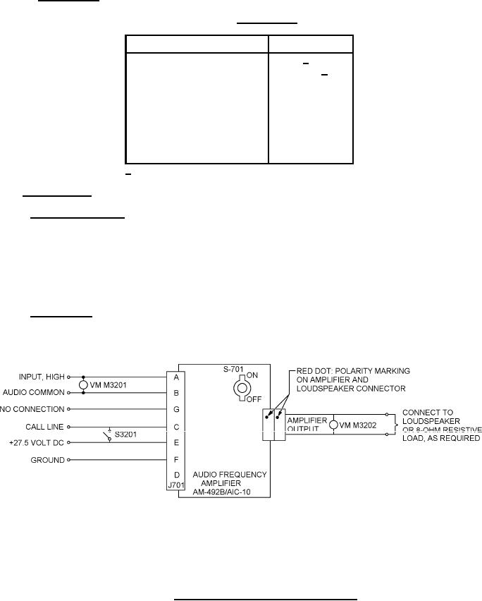
4.5.2 Electrical tests. The test circuit used shall be as specified on figure 6. The loudspeaker shall be mounted in
the housing with the amplifier during all performance tests. In conducting tests for the complete assembly, the
loudspeaker shall be connected to the amplifier (see 3.4.2.2).
NOTES:
1. Voltmeters shown are Ballantine model 300 series or equal.
2. Use isolation transformer to isolate oscillator ground from circuit ground.
3. Ground audio common at one point.
4. Connect wiring to prevent ground loops.
FIGURE 6. Dynamic loudspeaker test circuit schematic.
17
For Parts Inquires call Parts Hangar, Inc (727) 493-0744
© Copyright 2015 Integrated Publishing, Inc.
A Service Disabled Veteran Owned Small Business