MIL-DTL-9415B
3.4.1.4 Cable clamp. The loudspeaker lead wires shall be capable of withstanding a 5-pound pull in the direction
of the clamp axis without evidence of movement of the clamp or slipping of the wires in the clamp (see 4.5.3.2).
3.4.1.5 Terminal board. The terminal board shall be rigidly mounted to the loudspeaker, and shall have sufficient
ruggedness to withstand rough handling and usage. The design of the terminal board shall be such that the soldering
or unsoldering of the loudspeaker lead wires will not affect the connection of the voice coil leads either at the terminal
board or at the voice coil. Voice coil lead is the wire connecting the voice coil to the terminal board of the
loudspeaker.
3.4.1.6 Loudspeaker connector. The loudspeaker connector shall consist of either two individual sockets or a
single two-socket connector. Each socket shall fully engage and fit with a pin of 0.438-inch length (11.125 mm) and a
diameter of between 0.0905 inch (2.299 mm) and 0.095 inch (2.413 mm) as specified herein.
3.4.1.6.1 Connector weight. The weight of the connector shall not exceed 5 grams.
3.4.1.6.2 Connector dimensions. The dimensions of the connector shall be specified on figure 2.
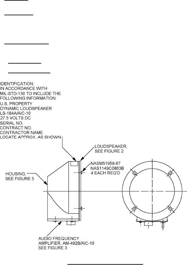
FIGURE 1. Loudspeaker assembly LS-184A/AIC-10.
3
For Parts Inquires call Parts Hangar, Inc (727) 493-0744
© Copyright 2015 Integrated Publishing, Inc.
A Service Disabled Veteran Owned Small Business